The projects developed by the Team of Timisoara at the 2005 Hard & Soft Contest Suceava, consists of three different approaches:
a) a hardware implementation of an elevator controller, containing a complete elevator operating algorithm which processes the necessary input sensor data, schedules the elevator’s movements and generates the necessary output data for the actuators, indicators etc;
b) a GUI based software simulation of the elevator operating algorithm;
c) a hybrid solution that implements state-of-the-art ideas in the field.
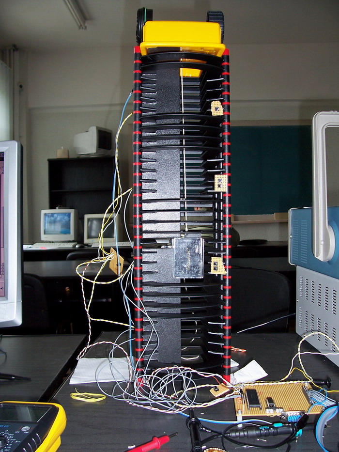
As an additional feature, we have also built a working scaled model of a real life elevator with four floors.
The solutions achieved during our contest work as described in the paragraphs that follow.
This solution implemented only one lift shaft. The shaft has 4 floors: ground floor and three others. Each floor has:
- Two buttons used for calling the elevator for going up or down;
- Sensors used to detect the presence of the cage;
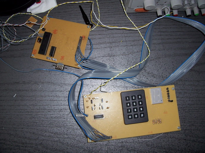
The cage buttons are implemented using a 12 contacts keypad. A system will be implemented for the detection of the presence of the passenger inside the cage.
There is a DC motor that is controlled through the PWM capabilities of the PIC microcontroller. Also there is a H – Bridge implemented to control the DC motor.
The majority of the outputs are simulated by the PIC microcontroller by sending the desired values on a RS232 interface to PC system. The PC runs an application that has the capacity to interact with the serial port. This application listens on the serial port for any incoming sets of data, retrieve the sent data, parse it and display the results on the GUI.
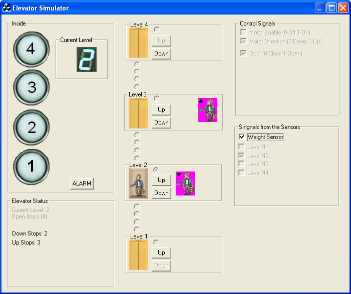
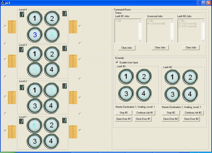
This solution is similar to the solution presented above with respect to the algorithms used, but it is a GUI driven simulation. This means that all the actuators, indicators, buttons, sensors, 4 floors and the cage will be simulated inside an environment developed in Visual C++ 6.0.
An additional feature of the current solution is the vocal announcement system for the passengers inside the cage.
This software solution is developed in Visual C++ 6.0 and the GUI is designed in order to comply with the way an actual elevator keypad looks like. For this reason non rectangular buttons are used inside dialog based applications that will incorporate the client application and the server application.
- Multiple elevator shafts: this solution implements two elevator
shafts instead of one as the other two solutions.
- First elevator shaft will be implemented in hardware, using parts of the first project;
- Second elevator shaft will be implemented in software, using parts of the second project;
- The two elevators are moving in tandem. Although they are not actually connected if one elevator moves in a direction, the other one is moving in the opposite direction.
- The floor numbers keypad that was situated on each elevator for the other projects is now situated on every floor. This gives the opportunity for a much better planning of the elevator’s movement.
- There is a dispatcher application that has “supreme” control over the elevators both in the case of an emergency and for manual override.
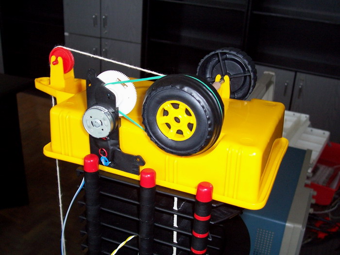
A scale model of an elevator is being built using a DC motor. The motor is controlled by the hardware board according to the commands received from the keypad and the floor buttons, based on a planning algorithm developed for the PIC microcontroller.
The DC motor is controlled by the PIC microcontroller using just 2 lines: one for speed and one for direction. In order to do this, a simple H – Bridge has been implemented in order to isolate the microcontroller from the large currents that are necessary to the DC motor when working under payload.
In order to have the elevator be more energy efficient, there is a counterbalance connected to the lift cage across the shaft of the DC motor. The weight of the counterbalance is half the weight of the maximum payload in addition to the weight of the elevator cage. This situation provides the DC motor with the opportunity to lift or descend only half the weight of the maximum payload, and not the weight of the filled elevator cage.